
In this lab we will explore the focusing properties of thin lenses using the framework of geometric optics. That is, we assume that light rays travel in straight lines in homogeneous media and are refracted and reflected as they pass from one medium to another. In this lab we are only going to be studying the refracted rays.
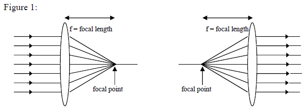
Consider a thin lens, whose surfaces are sections of a sphere. Refraction takes place both as light enters the lens and again as it leaves the lens. To first order, the overall effect is that if parallel rays enter a lens, then the rays leaving the lens converge to a point, called the focal point of the lens, as shown in Figure 1. The focal length \(f\), which is the distance from the lens to the focal point, is a characteristic of the lens, dependent on the curvature of its surfaces and the material’s index of refraction.
Using time-reversal symmetry (the fact that the laws of electromagnetism do not change if you run time backwards), light rays coming from – or passing through – the focal point will leave the lens parallel to the optical axis. This is also shown in Figure 1.
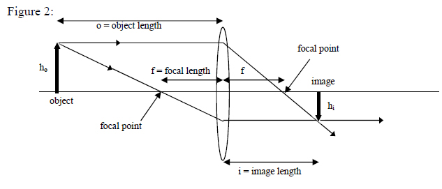
A lens can be used to form an image of an object, as shown in Figure 2. To determine where the image will be formed, we do not need to look at all light rays going through the lens. Using the two rays shown in Figure 2, one can see that the rays leaving a single point on an object come together at a single point where the image is formed. You can see in Figure 2 that the image is inverted and in general has a different height than the object. In addition to the two rays shown, there is a third ray that can easily be drawn. A light ray that goes through the center of the lens acts as if it continues on an undiverted path.
The Thin Lens Equation
- By comparing similar triangles in Figure 2, we can show that $$\frac{f}{i}=\frac{h_{o}}{h_{o}+h_{i}}~~~{\rm and}~~~\frac{f}{o}=\frac{h_{i}}{h_{o}+h_{i}}.$$ Here \(i\) is the distance from the lens to the image, \(o\) is the distance from the lens to the object, and \(h_{i}\) and \(h_{o}\) are the heights of the image and object respectively. We use the convention that the object distances are positive when the object is to the left of the lens (negative to the right), and that the image distances are positive when the image is to the right of the lens (negative to the left).
- We can combine the two equations above to derive the thin lens equation: $$\frac{1}{o}+\frac{1}{i}=\frac{1}{f},$$ which relates the positions of the object and image for a lens of focal length \(f\). This is today’s Key Equation.
- We can also show that the magnitude of the ratio of magnification, \(m=h_{i}/h_{o}\) (the ratio of image height to object height) is equal to the magnitude of \(i/o\) (the ratio of image length to object length).
Some Additional Discussion:
There are two focusing aberrations that we are not investigating in this Lab but that you should be aware of. First is spherical aberration. This is caused because rays further from the optical axis diffract more and converge to a point somewhat closer to the lens than the focal point.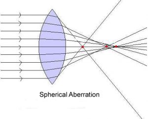
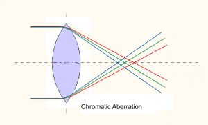
The other aberration is known as chromatic aberration. This is caused because the red end of the spectrum diffracts less than the violet end of the spectrum. A good way to remember this is the mnemonic device of the 3R’s: “Red Reduced Refraction”
Equipment Data Collection and Analysis
![]()
